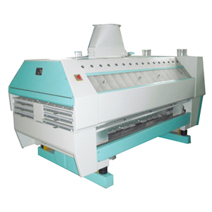
FMFQ Pneumatic Flour Mill
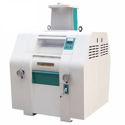
FMFQ-4~6×2 Pneumatic Flour Mills is our new developed medium flour milling machines. It adopts double arc flank profile belt. The series flour milling machine features balance transmission, low noise, no oil dirty, unique roll bearings equiped. Compared to normal roller mills, it is reliable in orientation, stable in working. Moreover, the flour milling machine is sensitive and exact when change the clutch gate of roller mills. It can controlled both by hand or pneumatic, which is very convenient in operation. The series flour milling machine use induced receiver for raw materail, with smaller resistance and convenient discharge of material. With motor inside, compact structure, the FMFQ series flour roller mills are completely closed in whole, thus the operation is very safe and reliable.
| Model | FMFQ-4×2 | FMFQ-5×2 | FMFQ-6×2 |
|---|---|---|---|
| roller Ø ×length (mm) | Ø250×400 | Ø250×500 | Ø250×600 |
| rmp of fast roller | 550~650 (tooth roller) 450 (smooth roller) | ||
| rmp of slow roller | 2.5-1.25:1 | ||
| material absorption tube Ø | Ø 60- Ø120 | ||
| equipped power (kw) | 4-11 | 4-15 | 5.5-18.5 |
|
overall dimension (mm) L×W×H |
1285×1500×1810 | 1385×1500×1810 | 1485×1500×1810 |
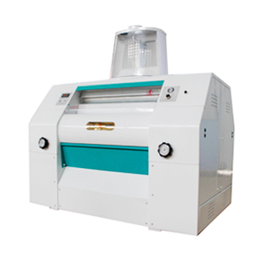
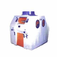
The FMFQ series Flour Milling Machine is one of mulriple type oblique pneumatic flour millinging machines. It have similar working theory as the MDDK flour mills. The rollers are oblique, featured adjustment of roll clearence and transmission etc. structure.
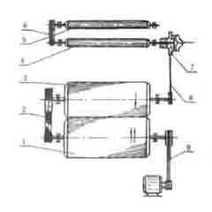
The structure of FMFQ Flour Mills
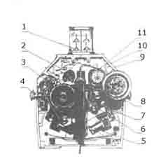
The Cutaway View of FMFQ Flour Mill
1. Sense float
2. Transmission of feeding roller
3. Double arc flank profile timing belt
4. Adjust handwheel
5. Clutch valve air cylinder
6. Bearing arm of slow roller
7. Adjusting Arm
8. V-belt of main transmission
9. Screw button of pneumatic control
10. Pneumatic Displayer
11. Pneumatic film clutch
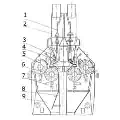
1. Sense float
2. Feeding Tube
3. Valve of feeding
4. Roller of Feeding
5. Fast Roller
6. slow roller
7. Cleaning device of grinding roller
8. Air absorption tunnel
9. Discharge hopper
Feeder
FMFQ flour milling machine has similar feeder as MDDK. The different is that the open or close of movable gate for feeding is directly drived by swivel arm moved by sense float.
Transmission Structure
Transmission of feeding roller is controlled by pneumatic film spring clutch. The speed control of roller use double arc flank profile belt, as Fig. F4-4. The transmission type combined the advantage of chaim and belt, featured stable working, extact in transmission ratio, low noise, free- lubricating, safe and sanitary etc. The different speed ratio pls note the following form of Timing Belt Pulley at Different Speed Ratio
| Speed Ratio | Teeth No. of Fast Roller Belt Pulley | Teeth No. of Slow Roller Belt Pulley |
|---|---|---|
| 2.5:1 | 50 | 125 |
| 2:1 | 50 | 100 |
| 1.79:1 | 56 | 100 |
| 1.51:1 | 66 | 100 |
| 1.25:1 | 80 | 100 |
| 1.12:1 | 80 | 90 |
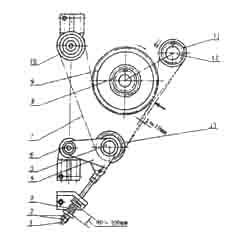
Cutaway View of FMFQ Flour Milling Machine
1. Fast Roller
2. Double arc flank profile timing belt
3. Slow roller
4. External roller
5. Inner roller
6. Single arc flank profile timing belt
7. Pneumatic film clutch
8. V-belt
9. Narrow V-belt
The Speed Control of FMFQ Flour Milling Machine
1. Tighten screw shaft
2. Screw Nut
3. Spring
4. Tighten Wheel Frame
5. Tighten Wheel Axes
6. Retaining ring 7. Double arc flank profile timing belt
8. Tighten flange
9. Big timing belt pulley
10. Guided pulley
11. Small timing belt pulley
12. Retaining ring
13. Tighten Wheel
Every pair of rollers adopt two pieces of double ar flank profile timing belt. When equipping, the sign of two belt should be kept on one line and the belt should be tighten by drag link nut for adjustment of tensioner pulley. Whether the belt is tighten affect the flour grinding machine greatly. The degree of tightening is tested by tensioner test device. When the valve closed, the belt should be pressed as Fig.F4-4. When load is 6.6kgf, the suitable displacement X=10mm. At this time, the length of spring is about 90~100mm. Timing belt can not be tighten too much, or it will make bearings damage prematurely.
The external roller of feeding roller is driven by slow roller, so the speed of feeding roller relates with diameter of driven belt pulley of feeding roller, rotary speed of fast roller and speed ratio of slow roller and fast roller.
The inner roll and external roll of feeding roller is driven by single air flank profile timing transmission. The transmission ratio is 1:3 between inner and external roller. The normal rotary speed of feeding roller is as the following:
| rpm of fast roller (r/min) | 650 | 600 | 550 | 450 | |||||||
|---|---|---|---|---|---|---|---|---|---|---|---|
| ratio of fast & slow roller | 2.5:1 | 1.25:1 | 2.5:1 | 1.25:1 | 2.5:1 | 1.25:1 | 1.5:1 | 1.25:1 | |||
| rpm of slow roller (r/min) | 160 | 96 | 242 | 148 | 88 | 224 | 135 | 81 | 205 | 140 | 133 |
Adjustment of Roll Clearance Setup
The structure of roll clearance adjustment device of FMFQ flour Milling Machines pls note Fig. F4-5. It use Multi-lever rod, direct driven by air cylinder to move bearing arm of slow roller to realize blutch valve. Thereinto, the supporting point of top riser frame is A, the supporting point of adjust arm is B, the supporting point of bearing arm of slow roller is C, and the supporting point of air cylinder is D.
When push rollers, air cylinder close to fast roller by screw shaft dragging bearing arm of slow roll. The position of slow roller is limited by top riser frame which the position can be adjusted of screw shaft. When roller moves back, the screw shaft leave off top riser frame.
During working process, adjust the handwheel to eject the top riser frame, which can press the piston of air cylinder retraction and increase the roller clearance sequentially. Contrarily, the roller clearance decrease. When hard material come into grinding room, the piston of air cylinder will be ejected because of increased pressure, which can protect the flour grinding machine.
Under the top riser frame, there is a limit adjusting nut equipped to protect rollers from knocking in working process.
The Adjustment Device of Roll Clearance of FMFQ Flour Milling Machine
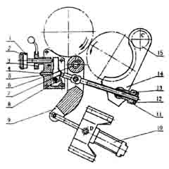
1. Supporting nail
2. Adjust handwheel
3. Tighten handwheel
4. Limit adjust nut
5. Tighten roller
6. Adjust Shaft 7. Small Top riser
8. Top riser frame
9. Adjust arm
10. Air cylincer
11. 12. Adjust nut
13. Bearing arm of slow roller
14. Supporting Axes
Absorption Device in Grinding Room
The discharge way of the roller mills have two kinds: one is auto flow discharge, the other one is adsorbing material by grinding room. The adsorption material of grinding room pls note the following Fig.F4-6.
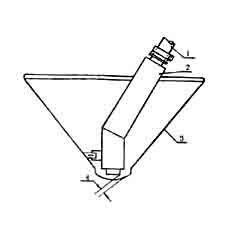
1. inner absorption tube
2. external cover tube
3. discharge hopper
4. clearance between material tube and hopper